Building a custom mechanical keyboard
2020-12-05, updated on 2021-09-12
About 4 years ago I started building buying parts for an ortholinear1 split2 mechanical3 keyboard. Inspired by
the likes of the Planck or Diverge keyboards I set about designing a simple layout with Keyboard Layout Editor and a top plate using Swill KB, with the plates cut by RazorLAB. I picked up some Gateron brown switches, a pro-micro controller and a few other bits and bobs. Apparently at that point I lost interest and there it sat.
Sometime between then and now, one of the plate halves was lost to an incident involving my foot. The other piece however survives to this day. Of course this piece alone is not big enough to be a real keyboard (no matter what some keyboard enthusiasts might tell you!) so it is destined to become an unnecessarily large macropad.
Now, I could just have another plate cut to make it a full keyboard again, however I am going to finish it as-is to:
- Practice (electronics, woodwork) for the next, much bigger, more robust board.
- I have all the parts already.
- Familiarising myself with QMK.
- It will be a relatively simple platform with which to play with making my own firmware. I'd like to see if I can do something with uLisp.
I will update this post with progress as I go, rather than splitting it into multiple posts.
What's the plan?
The basic idea is to:
- Hand-wire the keyboard. That is, the keyswitches will be supported by an acrylic plate and there will be no PCB. The wiring will be messy and the microcontroller (pro-micro) will be floating around in the case.
- The case will be a wooden block; probably softwood for this experiment. The block will be a little larger than the plate with the inside routed out. Where the plate rests will be slightly recessed so that the top of the plate is flush with the top of the wooden part of the case.
- The firmware will be QMK.
Wiring the rows
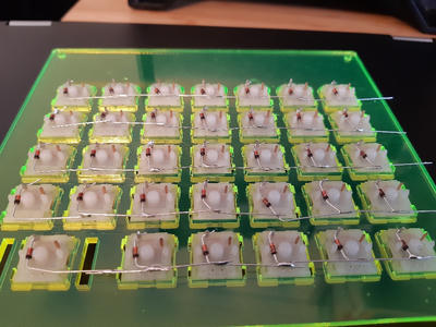
The first step was putting the switches into the plate and wiring the rows together. I did this solely using diodes as it is the standard way most people do this4. After I had done this, I found that people now tend to loop the diode around the switch pins so they don't move when trying to solder them, which would have made this far easier.
Wiring the columns
The next step was to wire the columns. For this, I'm using multi-core DuPont wires that I got in a bundle from eBay years ago as it's what I had lying around. I picked up a wire stripper that can strip the insulation in the middle of a piece of wire, so can use a single piece of wire for the entire column rather than having to solder multiple small pieces of wire for each column.

I soldered each gap, from one end to the other, moving the insulation to cover as much of the bare wire as possible after each part was soldered.
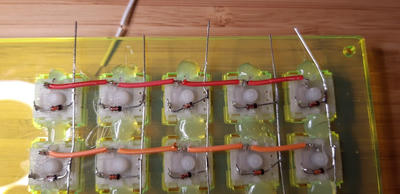
After all the columns and rows were wired, I checked continuity of each with a multimeter. All good!
Wiring the microcontroller
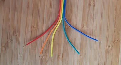
The final step was to wire the pro-micro to the rows and columns. For this I took some attached wires, and splayed and stripped the ends, keeping the joins in an attempt to make it a little neater.
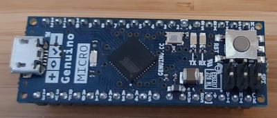
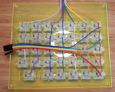
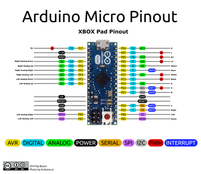
For testing, I left the push-fit connectors on the wires and attached them to the micro controller (which already had headers soldered). I used the following pinout diagram for reference.
I used 5 rows and 7 columns with the diode running columns to rows. The chip on the Micro is an ATmega32U4. Setting this up in Keyboard Firmware Builder yields the following:
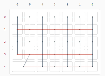
I wired the columns and rows to the pins on the Arduino like this. Columns were:
- 0: B0
- 1: B1
- 2: B2
- 3: B3
- 4: B4
And rows:
- 0: B5
- 1: B6
- 2: B7
- 3: D0
- 4: D1
- 5: D2
- 6: D3
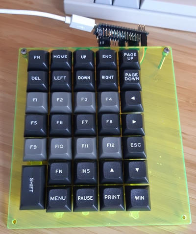
To make it look sort-of like a keyboard I then threw some spare DSA Dolch keycaps at it and this is what stuck.
Programming
Programming the keyboard was more of a pain than I expected. I intended to follow the QMK guide to the letter for simplicity. That guide is currently written making the assumption that you will use the QMK Toolbox to flash your micro controller, however for some reason it did not detect my Arduino. I tried various drivers, removing all the drivers and letting the toolbox install its own, but to no avail. The Arduino IDE however did reliably detect the controller, so I knew it worked. Ultimately, I think the problems are because of the device ID of my controller being 2341:8037 and that not being in the list of "known bootloaders" for QMK Toolbox. In that list, the Arduino Micro is listed with a device ID of 2341:0037 - different. I'm going to assume this is because my controller is a Genuino Micro (i.e. the non-US version). I suspect if my controller's ID was added, the toolbox would detect it and work correctly.
Obviously that would take some time and effort, so I pursued another avenue. I grabbed my laptop and travelled to the land of Linux where things make much more sense to me than they do in Windows. I did a bit of fiddling and documentation-reading, however the final recipe for getting QMK on to my controller looked a little something like this:
- Install
qmkusingpip --user install qmk. Accept all of its offers to install dependencies (we want it to just work after all). Make sure you copy the udev rule for ATmega32U4 devices when mentioned. - Download the zip file from KB Firmware (after you've imported your layout from Keyboard Layout Editor and set up your matrix, keymaps and pins).
- Extract this zip, copying the
./keyboards/kbfolder to~/qmk_firmware/keyboards/handwired/somename. - Edit
~/qmk_firmware/keyboards/handwired/somename/default/keymap.cand remove theaction_get_macroblock. I think this is because KB Firmware must build the code (or at least did when I was using it) for an older version of QMK. - Change into the
~/qmk_firmwarefolder and flash withqmk flash -kb handwired/somename -km default -bl avrdude. The docs don't usually mention needing to specify the bootloader, but I needed to. Perhaps it has been omitted from KB Firmware's output to be compatible with more devices? Once flashed (hopefully!), you will be prompted to restart your device. - You have a working keyboard!
Making it pretty
This will be a separate post because this one is already has a lot of information and images. The current plan is to use wood for the bottom of the case. I plan to take a block of wood (or a few sheets of ply sandwiched together for the prototype) and route out the middle for the switches/controller and have a shallow rim around the edge for the acrylic plate to rest on. Once I get to that, I'll link the new post here.
Thanks for reading! I hope it was at least interesting, if not useful.
Footnotes
Refers to keyboards where all keys are in aligned columns and rows. Not all keyboards are a precise grid, some will use aligned columns only with staggered rows (such as the Ergodox).
Where the left- and right-hand sides are physically separated.
Uses mechanical keyswitches rather than a rubber membrane.
See most custom builds, particularly the BrownFox